
Two products can both be advertised as carbon-fibre 3D printing while using very different technology. One is a conventional plastic filament containing short pieces of fibre. The other places long, continuous reinforcing strands into a polymer part using specialised equipment and toolpaths. The difference affects stiffness, strength direction, hardware, design freedom and price.
On this page
- The central distinction
- Why chopped carbon does not equal a carbon laminate
- Continuous fibre is directional
- Chopped fibre also changes print behaviour
- How should a functional part be designed?
- Strength numbers need context
- Which option is appropriate?
- Equipment and total cost
- What we would test
- The conclusion
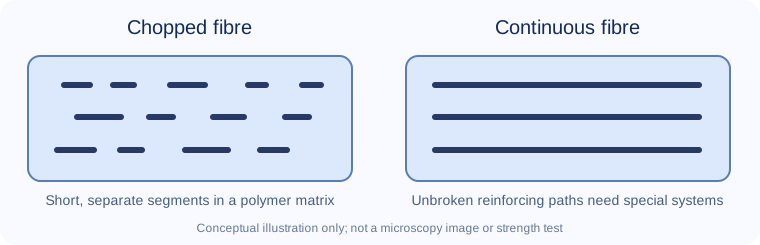
For an ordinary filament printer, buying a roll of PLA-CF, PETG-CF or PA-CF means buying a chopped-fibre composite unless the manufacturer explicitly says otherwise. It does not convert the machine into a continuous-fibre composite printer.
The central distinction
Chopped fibre: Short carbon segments are mixed into a molten thermoplastic. They flow through the nozzle and become distributed along the extrusion paths. Their length, concentration and alignment influence the finished material, but the matrix plastic carries much of the load and bonds the layers.
Continuous fibre: A purpose-built process places much longer carbon strands or tows in planned paths, sometimes alongside a separate polymer matrix. These can reinforce selected regions very strongly along chosen directions, if the toolpath, consolidation and design are appropriate. Markforged describes both its chopped-fibre-filled nylon base and separate continuous reinforcement technology.[1]
| Aspect | Chopped-fibre filament | Continuous-fibre reinforcement |
|---|---|---|
| Typical equipment | Compatible conventional FFF printer with hardened nozzle | Specialised printer and toolpath system |
| Fibre form | Short dispersed segments | Long reinforcing strands or paths |
| Design control | Mainly through ordinary extrusion roads | Placement and orientation of reinforcement can be designed |
| Common benefit | Stiffness, surface texture, dimensional behaviour | High directional reinforcement potential |
| Main limitation | Matrix and layer interfaces still dominate many failures | Cost, design constraints and directional properties |
| Cost and complexity | Potentially accessible to hobby and small workshops | Often industrial/commercial process |
This is a conceptual comparison, not a measured strength ranking. A carefully designed chopped-fibre part may be better suited to a particular task than a poorly oriented continuous-fibre one.
Why chopped carbon does not equal a carbon laminate
A carbon-fibre laminate typically contains long fibres laid in particular directions to carry loads. A chopped-fibre filament has discontinuous segments. They may improve stiffness, but they cannot transmit load along an entire printed wall in the same way as a continuous strand without depending heavily on the surrounding polymer.
Fibre-matrix bonding, segment length and orientation change how stress transfers through the composite. If the polymer softens with heat, the short fibres do not prevent all deformation. If a part is pulled perpendicular to printed layers, the interface may still be a weak point.
Markforged's technical explanations distinguish its chopped-fibre Onyx material from continuous fibre reinforcement, and its design guides emphasise orientation relative to load.[1][2] They make an important point for buyers: the word carbon is not enough to compare the two product categories.
Continuous fibre is directional
Continuous reinforcement can be highly effective when the fibres follow the main load path. Along a long tensile member, a well-positioned fibre path may carry substantial load. Across the fibres or through the printed thickness, behaviour can be very different. The material is therefore anisotropic, meaning its properties depend on direction.
The design may need minimum wall thickness, particular radii or specific interior regions to place the fibres. Tight corners, holes and sudden section changes complicate reinforcement routing. Not every shape permits an ideal fibre pattern, and not every volume can be filled with useful continuous strands.
The manufacturer's software, printer geometry and material data must be evaluated as a system. A headline strength figure from a favourable test coupon cannot be applied without qualification to a small complex bracket with fastener holes and layer interfaces.
Chopped fibre also changes print behaviour
Even though it lacks continuous reinforcement, chopped-fibre filament is not merely standard PLA or PETG with a black pigment. Carbon particles can abrade brass nozzles, alter viscosity, contribute to clogging and make the strand more brittle in feeding. Prusa's composite guidance calls for hardened nozzles and appropriate profile choices.[3]
The matrix remains critical. PLA-CF may be aesthetically appealing and relatively accessible, whereas PA-CF may need drying and a hotter, controlled environment. Some product formulations are designed more for matte appearance than extraordinary strength. The fibre percentage, shape and size differ, so use a named grade's TDS.
When comparing prints, inspect not only appearance but dimension, fracture, delamination and the effect of moisture. Chopped reinforcement can improve one property while reducing elongation or impact resistance.
How should a functional part be designed?
Begin with the load case: what force, in which direction, for how long, at what temperature and humidity? A fixture subject to occasional compression differs from a strap carrying repeated tensile cycles. A bracket held by screws also experiences concentrated stresses around holes.
With chopped-fibre FFF, orient the part to keep major loads in stronger printed directions where practical, use sufficient walls and avoid unsupported thin bosses. With continuous reinforcement, work within the system's fibre-placement constraints and orient the reinforcement toward the actual load paths.
Neither method is automatically safe for flight-critical, lifting, pressure or medical equipment. Those applications require qualified material, process controls, part inspection and appropriate engineering sign-off.
Strength numbers need context
When a supplier claims a large multiple of strength or stiffness, look for the comparator and test method. Is it the same base plastic without continuous reinforcement? Was it a tensile sample loaded along the fibre? How was the print conditioned? What was the fibre volume, layer direction and failure mode?
Markforged publishes performance comparisons for its specific systems, but those claims apply to the stated equipment, material and specimens.[4] They are not independent measurements of every carbon-fibre printer or a guarantee for every geometry.
For purchase comparisons, place data side by side only when the same property and test standard were used. A bending modulus, tensile strength and impact energy are not interchangeable.
Which option is appropriate?
Matte covers and light fixtures: Chopped PLA-CF or PETG-CF may be enough if the printer supports abrasive materials. Continuous fibre would add unnecessary complexity.
Workholding jig or modest mechanical bracket: Chopped PA-CF or another engineering composite can be useful, subject to part testing and environment.
High load along a known direction: Continuous reinforcement may offer a meaningful benefit where a compatible machine can place fibres strategically. Compare cost and process with machined metal or conventional composites too.
Complex multidirectional loading: Neither label alone is sufficient. Analyse load paths, joints and failure modes, then use representative tests.
Prototype for appearance: A basic matte unfilled filament might deliver the same visual goal at lower cost and without wearing an ordinary nozzle.
Equipment and total cost
Chopped-fibre entry cost is often a wear-resistant nozzle and suitable filament, plus a dryer or enclosure for demanding polymers. An industrial continuous-fibre setup can involve a specialised machine, proprietary materials, maintenance and trained process design. The cost of failed parts, testing and throughput belongs in the calculation.
Before upgrading, establish a clear mechanical target. A beautiful stiff sample may not justify new equipment if an ordinary PETG part already meets the requirement. Conversely, a safety-critical component may demand a professionally qualified process beyond either consumer option.
What we would test
A fair physical comparison would choose a specific load case and design separately for each process, then document printer, materials, fibre orientation, conditioning and test standard. Multiple specimens would be loaded in the intended and weaker directions. Failure modes, scatter and manufacturing cost would be recorded.
We have not run such tests for this article. The explanation distinguishes technologies using manufacturer documentation; it does not turn promotional strength claims into independent experimental findings.
The conclusion
Chopped carbon-fibre filament is a fibre-filled thermoplastic suited to compatible conventional printers. Continuous-fibre printing is a reinforcement process that deliberately places long strands, often in a specialised machine. Choose according to actual loads, direction, process limits and cost—not just the shared carbon-fibre name.
Sources
[1] Markforged — Continuous carbon-fibre printing overview
[2] Markforged — Composites design guide